FAIRFIELD, N.J. — November 16, 2024
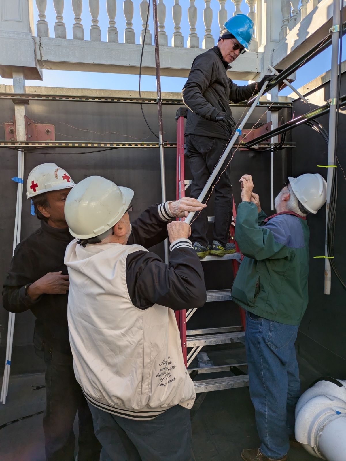
Beneath a brilliant November sun at the American Red Cross facility in Fairfield, New Jersey, members of the West Essex Amateur Radio Club (WEARC) gathered in the early afternoon to install a new high-frequency (HF) antenna—a critical tool that promises to enhance communication capabilities at the facility, particularly during emergencies.
The installation team consisted of a small but enthusiastic group of WEARC volunteers, who worked with precision and camaraderie against the backdrop of an unseasonably warm day. “It’s not often we get this kind of weather in November,” one member remarked. “It’s a perfect day to be up on a roof with an antenna project.”
The Antenna: A Versatile Wire-Based Solution
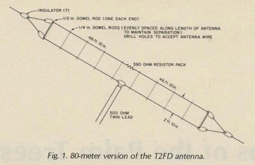
The chosen antenna, constructed by Jerry WB2GZL, is based on a design published in 73 Magazine from May 1984 called the Tilted Terminated Folded Dipole (T2FD). It is similar in design to a terminated wide-band folded dipole and is renowned for its versatility and wide frequency coverage. Unlike traditional resonant antennas, the T2FD is a non-resonant antenna, which means it requires the use of an antenna tuner to match impedance and achieve efficient operation. This design allows for multiband operation without significant changes to the antenna itself, making it an appropriate choice for emergency communications where flexibility is paramount
The T2FD’s design employs a folded dipole configuration, consisting of two parallel conductors joined at each end to create a continuous loop. A distinctive feature of the T2FD is the inclusion of a non-inductive terminating resistor, typically in the 500 Ohm range when the antenna is fed with 450 Ohm ladder line, which absorbs non-radiated energy and prevents signal reflections. This resistor, combined with the broad impedance bandwidth of the folded structure, ensures the antenna can perform sufficiently over a wide range of frequencies.
Constructed with weather-resistant materials, the T2FD installed at Fairfield spans a significant length, maximizing coverage and signal strength. The antenna’s use of a 450-ohm ladder line feed, paired with a roof-mounted balun and 50-ohm coaxial cable run into the radio shack, provides a low-loss, efficient transition from antenna to radio equipment.
The evolution of the T2FD antenna, a fascinating innovation in the world of radio communications, has been meticulously chronicled in amateur radio literature over the decades. Its early conceptualization was explored in a June 1949 issue of QST, where its unique attributes and potential applications were first presented to the amateur radio community. This initial discussion prompted subsequent analyses, with follow-up articles appearing in the November 1951 and February 1953 issues of CQ Magazine. Decades later, the enduring relevance of the T2FD was reaffirmed in the pages of 73 Magazine in May 1984, offering a contemporary perspective on its utility and design. These writings collectively highlight the enduring curiosity and ingenuity that have long defined the amateur radio tradition.
Comparing the T2FD and the Traditional Folded Dipole
While the T2FD shares structural similarities with the traditional folded dipole, their operational principles and use cases differ significantly.
Resonance vs. Non-Resonance
– The traditional folded dipole is a resonant antenna, designed to operate efficiently on specific frequencies without the need for an external tuner. Resonance is achieved by carefully matching the antenna’s physical length to the wavelength of the target frequency, typically resulting in low standing wave ratio (SWR) at the resonant point.
– The T2FD in contrast, is non-resonant. Its design, featuring a terminating resistor, broadens the operating frequency range but sacrifices resonance. An antenna tuner is required to match the antenna’s impedance to the transceiver’s output, enabling efficient energy transfer.
Bandwidth
– The traditional folded dipole provides excellent performance on its resonant frequency and, to a lesser extent, harmonics. However, its usable bandwidth is narrow, often limiting its versatility.
– The T2FD offers significantly broader bandwidth, supporting efficient operation across multiple HF bands. This makes it highly advantageous for applications where rapid frequency changes are necessary.
Efficiency
– The folded dipole is highly efficient within its design frequency range, as nearly all the transmitted energy is radiated.
– The T2FD sacrifices some efficiency due to the energy absorbed by the terminating resistor. This trade-off is offset by its flexibility in multiband operation, particularly in emergency or general-purpose communication setups.
Complexity
– The traditional folded dipole is simpler to install and does not require additional components like a tuner or terminating resistor.
– The T2FD, while more complex, is a robust solution for scenarios requiring adaptability, as seen in the Fairfield installation.
Installation Details: From Roof to Shack
The T2FD antenna is fed with 450-ohm ladder line, known for its minimal signal loss during transmission and reception. The ladder line terminates at a balun (balanced-to-unbalanced transformer) mounted on the roof, matching the impedance to a 50-ohm coaxial cable, which then runs down to the radio room on the first floor. This configuration ensures compatibility with the Red Cross’s vertical coaxial riser while maintaining efficiency.
Next Steps: Testing and Integration
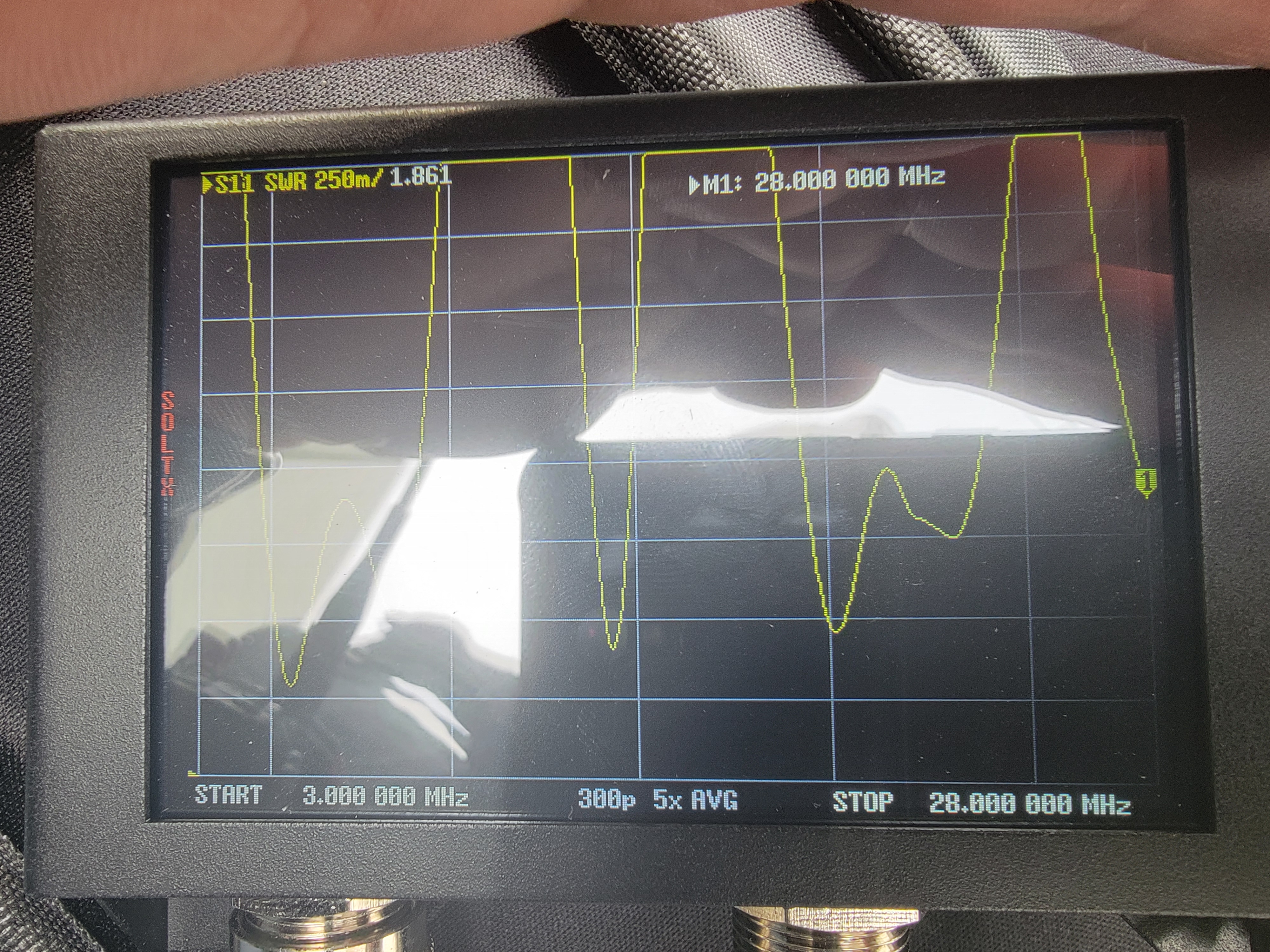
The antenna, though installed, has not yet been tested. Testing is scheduled for a future weekend, when WEARC members will evaluate its performance across multiple HF bands. These tests will involve verifying the antenna’s impedance matching, confirming signal radiation patterns, and ensuring compatibility with the Red Cross’s communication protocols. The use of an external antenna tuner will also be validated during these trials.
Once testing is complete, the antenna will be fully integrated into the Red Cross’s emergency communication system, standing ready to support disaster relief efforts with reliable, global communication. As the new antenna broadcasts its signals across the airwaves, it will carry a message of collaboration, adaptability, and community resilience.