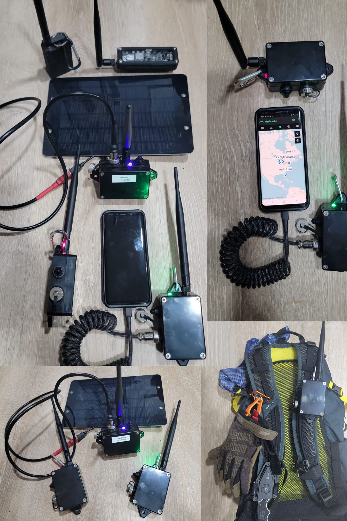
Let’s build my version of the LoRa Meshtastic ESP32 device. What do we want to achieve:
1. As waterproof as it can be.
2. No 3D Printed needed.
3. Battery that can run for a couple days.
4. Easy USB waterproof connector that can be used for charging.
5. ON/OFF switch WITH LED ON/OFF indicator
6. High gain antenna.
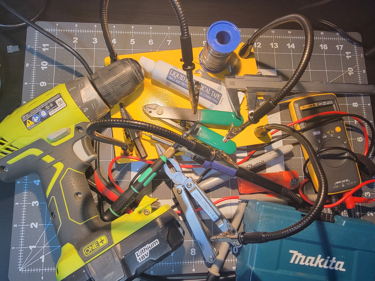
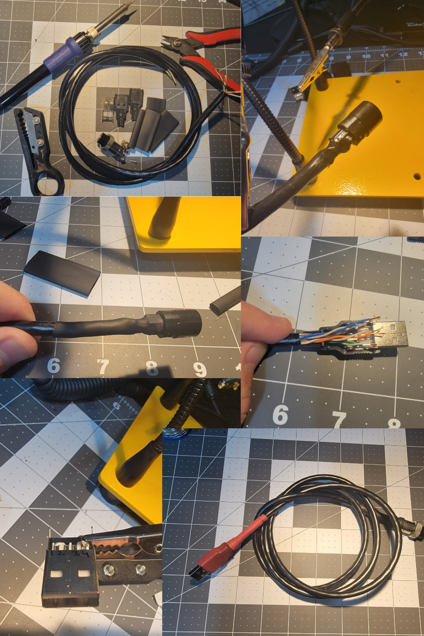
Tools needed below (just look at the picture below):
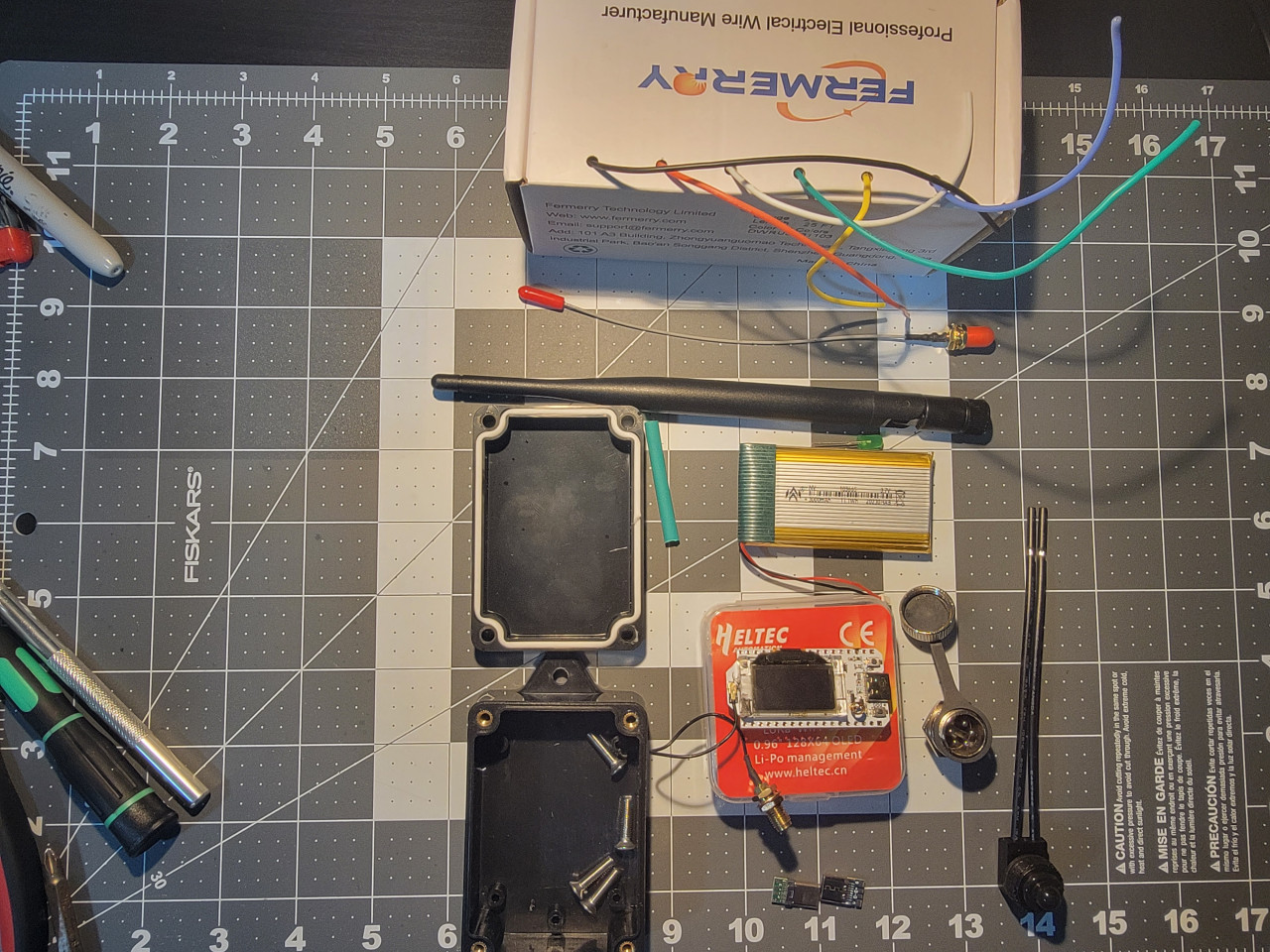
Parts that you will need:
ALL AVAILABLE ON AMAZON!
915MHz ESP32 LoRa 0.96 OLED Development Board V3 SX1262 Type-C
915MHz LoRa Antenna Omni 5dbi Gain SMA Male for ESP32 LoRa OLED Board
MakerFocus 4pcs 3.7V 3000mAh Lithium Rechargeable Battery 1S 1C Lipo Battery with Protection Board
mxuteuk 5pcs 12V RV Waterproof Push Button Switch Black ON/Off SPST Switch with 4.52inch Lines for RV/Motorcycle/Car MXU-KP-107
10PCS USB 3.1 Type C Connector 24 Pins Male Female Plug Socket Receptacle Adapter to Solder Wire & Cable 24P PCB Board Support Module
VizGiz 10 Pack USB Plug Replacement 4 PIN Type A Female Male Socket Connector Solder Terminal Repair
DKARDU 6PCS GX16 5 Pins Aviation Connector Male/Female Panel Aviation Wire Connector Plug Socket for Power Connection with 6PCS Waterproof Cover
Zulkit Junction Box ABS Plastic Dustproof Waterproof IP65 Universal Electrical Boxes Project Enclosure with Fixed Ear Black 3.27 x 2.28 x 1.30 Inch
DiCUNO 450pcs (5 Colors x 90pcs) 5mm LED Light Emitting Diode Round Assorted Color
22 AWG Stranded Wire Silicone Tinned Copper Wire Spool 25ft Each 6 Colors Flexible 22 Gauge Hook up Electrical Wire Kit from Fermerry
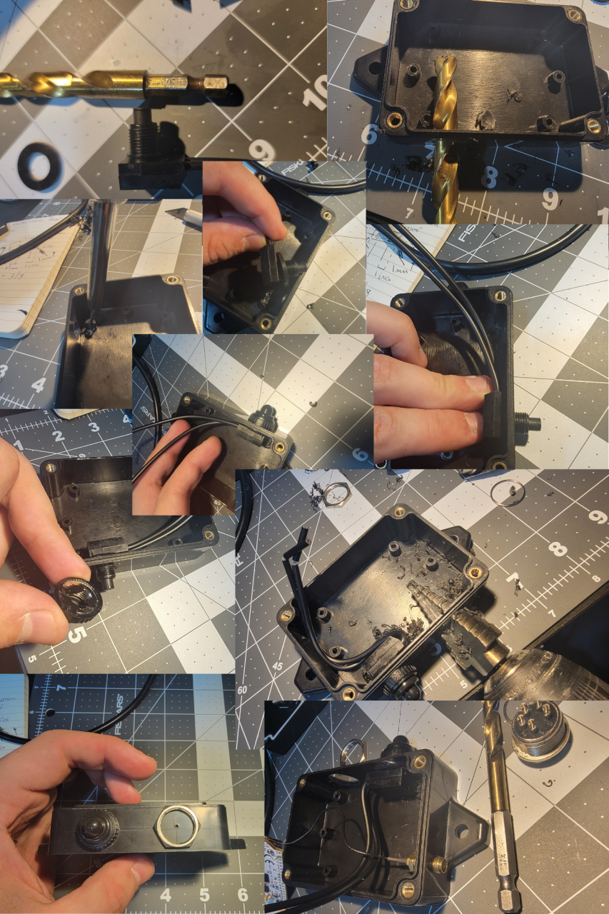
STEP 1 – Case
Let’s drill the box:
Mark one of the sides, from lower chanel of the top down, it’s 20mm tall. Do 2 lines, one at 10mm another 7.5mm from the top. The 10mm line is the guide for the switch, the 7.5mm from the top one is for the GX16 5 pin connector. Mark 1 inch from each side crossing the 2 previous lines.
With a soldering iron, do some guiding holes. The one on the bottom line 10mm is for the switch, the other one is for the GX16 connector. At the top, mark a place for the antenna SMA connector. We can drill the LED hole in a few.
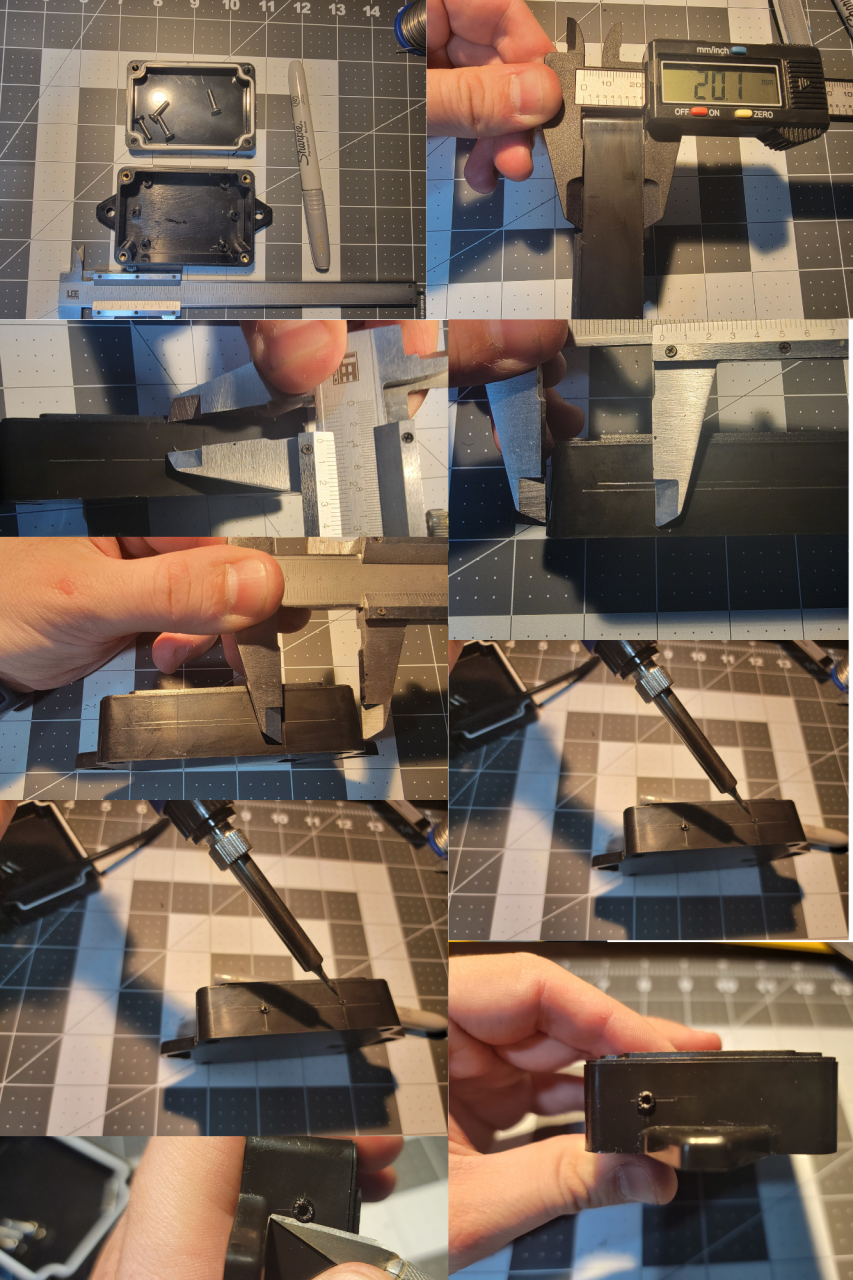
Switch is 3/8”, use a step drill for the GX16, 5/8” is the hole size. I used some liquid electrical tape to help with the water proofing. Don’t forget the rubber washer inside of the switch. The SMA connector is a 1/4” and the LED is 3/16”, it’s one of the final holes, in the next section, add where you want.
I had to use the soldering iron to remove a post that was in the way of the On/OFF switch.
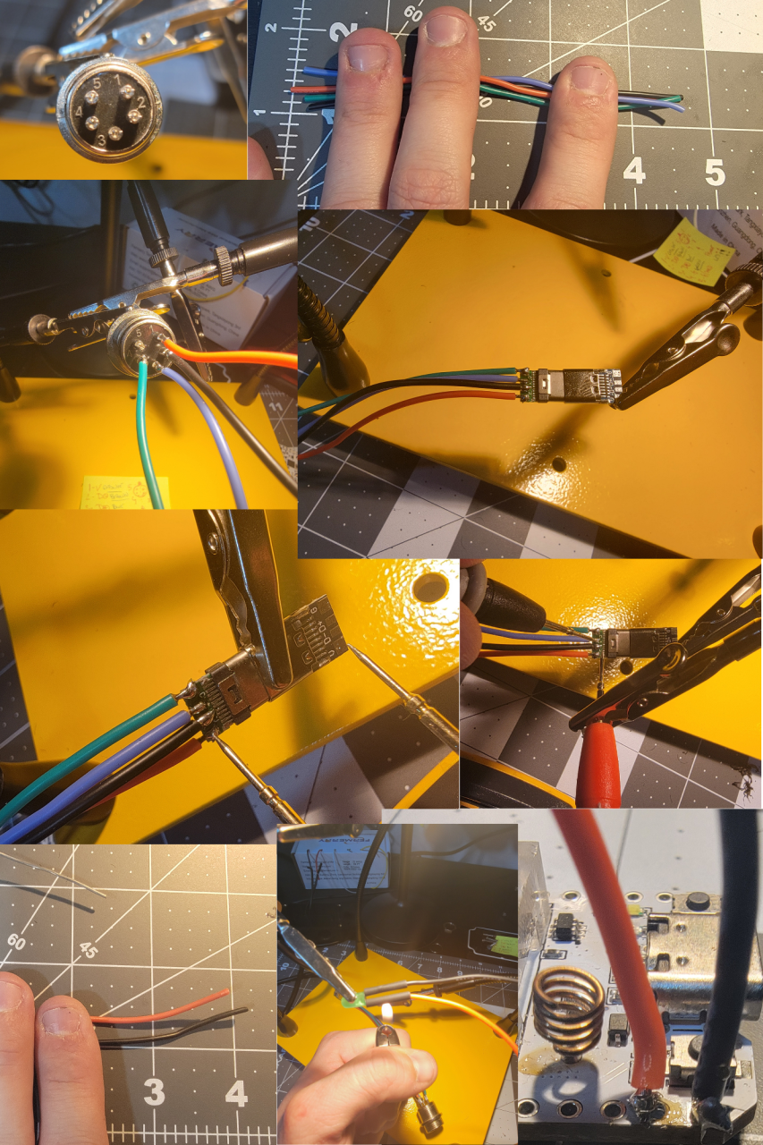
STEP 2 – Soldering connectors
The GX16 has some numbers. You can do whatever combination of color you want.
My setup is:
1 – RED (+V)
2 – B BRROW/BLACK (Data – )
3 – Blue (Data +)
4 – Green (Ground or V-)
5 – Nothing, no connection
4 1/2” should be enough for the the connection between the USBC and the GX16, same for the LED. LED is connected to the 3V and ground pins of the ESP36.
For USB-C side I kept the male and female connected just to see better and also to test for wrong connections / soldering bridges between the 4 connectors. ALWAYS check. There should be NO continuity between the 4.
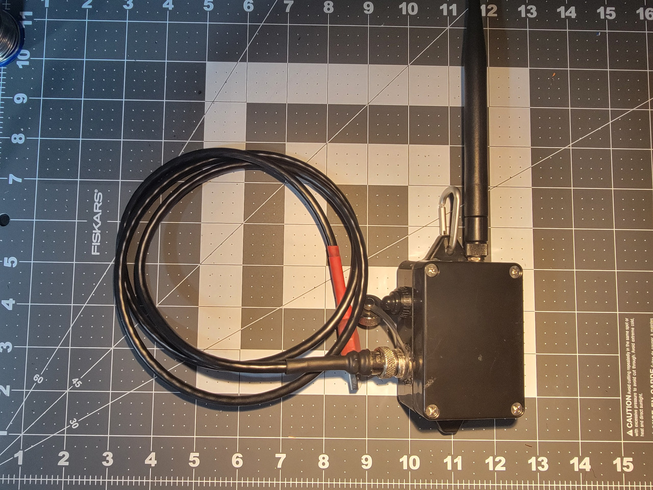
STEP 3 – Final Device assembly
Cut one of the battery cables and connect to the switch. Drill the final LED hole 3/16” and use super glue to keep the LED in place. It’s a snug fit and the super glue also helps with the waterproofing. The way it fits the best is with the ESP32 board below the battery.
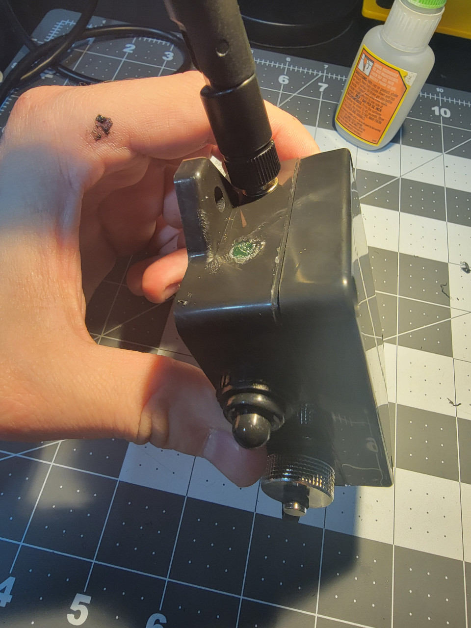
IMPORTANT: Before connecting the battery, connect the antenna. NEVER turn on the device with the antenna disconnected. Make sure you use the switch off after testing and close everything. Device is done.
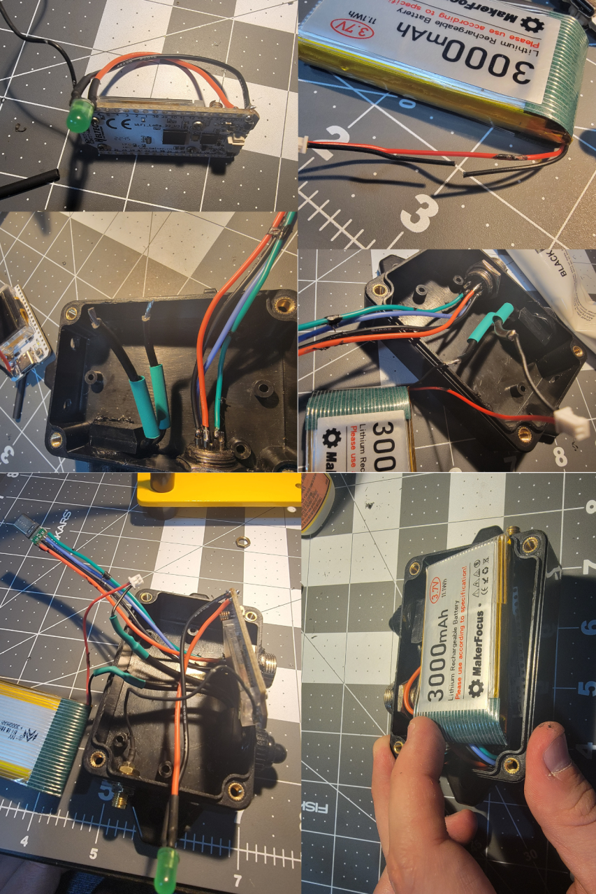
Almost done… The GX16 cap has a rubber, I added some super glue between the base of the connector and the rubber seal to keep the cap from falling when cap is open. Screw the lid of the case and it’s done.
STEP 4 – USB Cable for Data and Charging
Use whatever cable with 4 or more wires/conductors. I’m using a Cat 6 POE Ethernet Cable Waterproof Heavy high Speed LAN Network. It’s 4 pairs so I twisted the ends together of each pair. Numbers are in the male connector of the GX16 connector.
Use plenty shrinking of tube. I used 2 layers begore closing the GC16 connector so the metal part grips the cable well. Also used liquid electrical tape to make sure things stay in place and don’t short in case cable is pulled.
1. 5V + (Orange + White with orange Stripe)
2. Data – (Brown + White with brown stripe)
3. Data + (Blue + Blue with white stripe)
4. Ground AKA 5V- (Green + Green with white stripe)
TIP: Number the USB male connector: White plastic on top, left to right (1,2,3,4)
IMPORTANT:
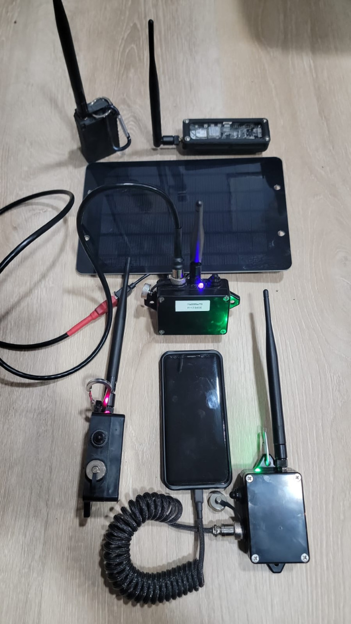
DEVICE WILL ONLY CHARGE WHEN ON/OFF SWITCH IS ON so you can connect via USB to charge in a solar panel, power bank or anything else you want. Add a carabiner to hand in your backpack, tree etc.
DONE!!!! Congratulations!!!
Connect to your computer, go to https://flasher.meshtastic.org/ and flash the most recent stable version of Meshtastic online.
IMPORTANT:
DEVICE WILL ONLY CHARGE WHEN ON/OFF SWITCH IS ON so you can connect via USB to charge in a solar panel, power bank or anything else you want. Add a carabiner to hand in your backpack, tree etc.
You are responsible for things you do. Any error, please leave a comment and this remember this is an AMATEUR GUIDE so it’s your responsibility to make sure you don’t do anything stupid. This contains a LITHIUM BATTERY and will be connected to a COMPUTER so there are risks. I’m showing how I did and worked for me, result may be different for you. Don’t cut, drill or burn your fingers, house etc. BE CAREFUL!
73
KD2WWU
Leave a Reply